| source Image |
Drawing in AutoCAD drawing can be done in principle freely without specifying coordinates. Dots and lines can be placed anywhere. Ignoring the coordinate system in the drawing of simple objects may not be a problem. But in drawing more complex objects and detail, the principles of the coordinates will definitely be a big problem.
AutoCAD coordinate system in essentially the same as the coordinate system in general World Coordinate System (WCS). Only a slight difference in a person who operates the point of view, the coordinates in AutoCAD can be divided into two, namely the absolute coordinates and relative coordinates.
Absolute coordinates are the coordinates of a reference to a single point (0,0,0) which by default is located in the lower left corner of the screen. Point (0,0,0) is a reference to any absolute coordinate placement. The use of highly accurate absolute coordinates for the depiction of objects, but less efficient in descriptions of complex objects. Because for every start line and the point should take into account the point (0,0,0) which may already be too far from the image area.
Relative coordinates, as the name refers to the relative coordinates are relative to the specific points that we have set themselves, and certainly no longer pay attention to the initial point (0,0,0). In this case the point used is the last point that has been selected. Characteristic of relative coordinates is the use of the @ in the early writing of coordinates to AutoCAD.
In practice, the coordinates in AutoCAD is not much different from the coordinate system that we often use the science of geometry. The use of common coordinates in AutoCAD include:
A. Cartesian coordinates
Cartesian coordinates has three main axes X, Y and Z. Value of X is the horizontal distance / horizontal. Value of Y is the vertical distance, being tilapia which Z is the distance away from the XY plane. In the default condition of the positive Z direction is heading towards Drafter (draftsman). Examples of the use of Cartesian coordinates in AutoCAD are as follows:
1. Click the Line menu, or type a line in the command line, then Enter
2. At the command line will show up comments "specify first point:" type 0.0 and Enter
3. "Specify next point or [Undo]: 4.0 enter
4. "Specify next point or [Undo]: 8.4 enter
5. "Specify next point or [Close / Undo]: 8.0 enter
6. "Specify next point or [Close / Undo]: 8.4 enter
7. "Specify next point or [Close / Undo]: 0.0 or C and enter
C (Close) means to close the location coordinates back to the beginning.
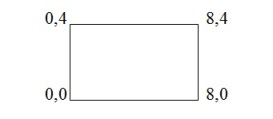 |
| Image 1.1 The use of cartesian coordinates |
B. Polar coordinates
Polar coordinate system using the rules of the angle and direction of displacement in the image area, or often interpreted the distance and angle of the destination point. Writing by means of "distance <angle". For example: 4 <60, this means a distance of 4, the angle 60. Follow these steps and See Image 1.2 for more details:
1. Click the line or type line, enter
2. Click anywhere on the screen
3. "Specify next point or [Undo]: @ 4 <60 enter
4. This means we make a line of length 4.0 and angle of 60.
Keep in mind that AutoCAD uses angle calculation system Counter Clock Wise (CCW) or counter-clockwise direction, the default condition. With the calculation of 0 or 360 is a horizontal line.
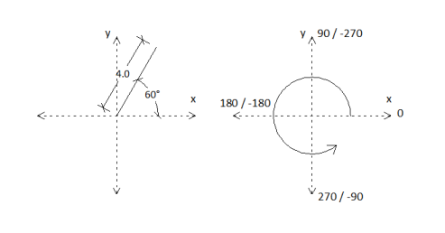 |
| Image 1.2 Polar coordinates |
Angle calculation is positive if counterclockwise hours. However, it is possible tocalculate the angle by clockwise (Clock Wise). To calculate a clockwise manner,then the calculation of a negative computed. So that means if the angle+270 = angle -90.source in Indonesia
No comments:
Post a Comment